Machines are all around us. A machine is something that makes it easier for us to do work such as moving heavy objects.
A printable PDF of the information on this page is available in the right-hand column.
Simple machines
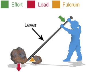
Diagram 1 - example of a simple machine
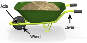
Diagram 2 - example of a compound machine
There are generally two types of machines: simple and compound. Simple machines are ones which have only one part to do the work (e.g. the lever in Diagram 1) and compound machines are those that have two or more simple machines working together to do the work (e.g. the wheel barrow in Diagram 2).
Simple machines help us by giving us a ‘mechanical advantage’. This means that we can do things with less effort if we use a simple machine. Imagine that you need to move a large, heavy load (e.g. a rock). You could try and do this alone, but that would take a lot of strength and effort. However, if we use a simple machine we gain a mechanical advantage. In Diagram 1 you can see how a crowbar acts as a lever to help us move the large load (the rock).
Keep reading to find out about a number of different simple machines.
Inclined planes
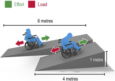
Diagram 3 - example of an inclined plane
An inclined plane is a flat surface that is at an angle to the load. This type of ‘machine’ has no parts that move.
An example of an inclined plane is a ramp. In Diagram 3, the ramp makes it easier for the person in the wheelchair (the load) to move up into a building. The steeper the slope of the inclined plane, the more effort it takes to move the load up the slope. Along with ramps, stairs are also an example of an inclined place. You would agree that it is much easier to walk up a ramp or a staircase than a ladder. The inclined plane gives us a mechanical advantage.
Some other examples of inclined planes include:
- roads leading up slopes
- ramps in car parks
- slides in playgrounds.
Levers
A lever is a rigid bar that rotates around a fixed point. This balancing point is called the fulcrum. A lever uses a force (or effort) to make a load move.
There are different types of levers, depending on where the load, the effort, and the fulcrum (balancing point) are positioned. For this reason, levers are classified into 3 separate groups: Class 1, Class 2, and Class 3.
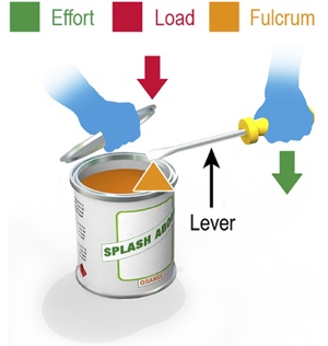
Diagram 4 - example of a class 1 lever
Class 1 lever: This is where the fulcrum is between the load and the effort.
An example of a class 1 lever is using a screwdriver to open a can of paint (Diagram 4). Here the screwdriver is the lever and pushing down on it raises the load (the paint can lid). Imagine how much harder it would be if you had to lift the lid with just your fingers.
Other examples of Class 1 levers include:
- bottle openers – to open a bottle of drink
- claw hammers – to pull out nails.
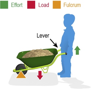
Diagram 5 - example of a class 2 lever
Class 2 lever: This is where the fulcrum is at one end of the lever, the effort is at the other end, and the load is in between.
An example of a class 2 lever is a wheelbarrow (see Diagram 5). In this case the wheelbarrow and its handles are the lever, the load is the weight in the wheelbarrow, the fulcrum is the axle and the effort is the force applied by the person lifting the handles.
Other examples of Class 2 levers include:
- staplers
- nutcrackers that have the hinge at the end of the machine.
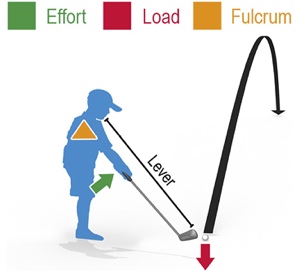
Diagram 6 - example of a class 3 lever
Class 3 lever: This is where the fulcrum is at one end of the lever, the load is at the other end, and the effort is in between. These levers involve using a large effort to move a small load a long distance.
An example of a class 3 lever is a person playing golf (see Diagram 6). In this case the lever is the golf club plus the person’s arms, the fulcrum is the golfer’s shoulder, the effort is the force being applied to the golf club by the golfer’s hands and the load is the weight of the golf ball.
Other examples of Class 3 levers include:
- using a cricket bat, tennis racquet or a hockey stick to hit a ball
- using a fishing rod to cast a fishing line.
Levers in balance
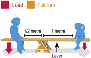
Diagram 7 - example of levers in balance
A see-saw is actually a lever with a fulcrum (balancing point) in the middle (see Diagram 7). Think about a see-saw with two people sitting at different distances from the fulcrum. If one person is twice as heavy as the other, the lighter person must sit further away from the fulcrum than the heavier person for the see-saw to be balanced. Once balanced, it requires very little force for each person to push the see-saw up and down with their legs.
Wheels and axles
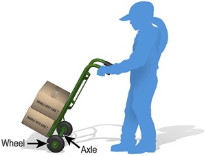
Diagram 8 - example of wheels and axles
A wheel and axle is a simple machine that is made up of a smaller cylinder (the axle) joined to a larger cylinder (the wheel). Often a wheel and axle is used to make it much easier to move a load. An example of this is a trolley, or any other wheeled vehicle (see Diagram 8). You will agree that it is much easier to move a heavy load across the ground with a wheeled vehicle.
Pulleys
A pulley consists of a rope (or a belt or chain) that passes around a wheel.
Fixed pulleys

Diagram 9 - example of a fixed pulley
An example of a fixed pulley would be the ones we see at the top of flagpoles (see Diagram 9). The pulley at the top allows the person standing on the ground to hoist the flag by pulling on the rope. This is much easier than having to climb the flagpole!
Other examples of fixed pulleys include:
- the pulley at the top of a yacht mast which allows the sail to be raised up the mast by pulling down on the rope
- the pulley at the end of the boom of a crane which works by pulling upwards to lift the load.
Moving pulleys
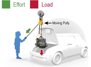
Diagram 10 - example of a moving pulley
Diagram 10 shows one moving pulley attached to the engine (the load), and one fixed pulley attached to the support above. This type of pulley system is called a ‘block and tackle’, where ‘block’ refers to the pulleys and ‘tackle’ is the chain that the person is pulling to lift the engine.
Wedges
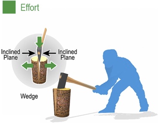
Diagram 11 - example of a wedge
A wedge is a simple machine that looks like two inclined planes joined together.
A good example of a wedge is an axe, where the head of the axe is made up of two inclined planes which do the work. Think about an axe being used to chop and split a piece of firewood (see Diagram 11). The axe is actually being used to change the direction of the force. The force of the axe blow is downwards, but the wedge changes this downward force into two sideways forces, causing the wood to split apart.
Other examples of wedges include:
- a knife blade
- a chisel
- the point at the end of a nail
- a doorstop that is wedged under a door to prevent it from moving.
Screws
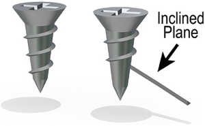
Diagram 12 - example of screws
A screw is an inclined plane that is coiled around a shaft (see Diagram 12). They usually have one flat end and one pointed end.
Examples of screws include:
- wood screws
- the screw in a car jack
- the screw on the lid of a jar
- the blades of a fan
- the blades of an aeroplane propeller.
Gears
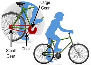
Diagram 13 - example of gears
Gears are toothed wheels that fit together so that when one gear turns it also turns the other gear. Sometimes the gears fit directly together, but other times they work together through a chain or a belt (see Diagram 13).
Some examples of the use of gears include:
- mechanical clocks
- car gearbox and drive systems
- electric drills.


